


Following the publication of the International Mining October issue and, more specifically, the annual in-pit crushing and conveying feature, we have taken a closer look at one of the core elements that makes up these systems, apron feeders.
In mining, apron feeders play a major role in ensuring smooth operations and increasing uptime. They are very diverse in their application within a mineral processing circuit; however, their full capabilities are not widely known throughout the industry leading to many raised questions.
Martin Yester, Global Product Support of Bulk Products at Metso, has answered some of the more important ones.
What is an apron feeder and when should it be used?
In simple terms, an apron feeder (also known as a pan feeder) is a mechanical type of feeder used in material handing operations to transfer (feed) material to other equipment or extract material (ore/rock) from storage stockpiles, bins or hoppers at a controlled rate of speed.
These feeders can be used in a variety of applications in primary, secondary and tertiary (reclaiming) operations.
Apron feeders are the preferred feeder for several reasons. Some of these are:
- Aprons provide better feed control to prevent material feeding in downstream equipment from choking;
- They can absorb the shock of loading material directly onto the feeder with a shallow bed (the impact coming down on the feeder when the material is dumped is great); and
- Apron feeders can reclaim a variety of dry or wet materials of various sizes at a uniform rate, with this flexibility applied in many applications.
What are the advantages of using a tractor chain style apron feeder?
A tractor chain style apron feeder refers to the undercarriage chain, rollers and tail wheels that are also used in bulldozers and excavators. This style of feeder dominates the market in industries where users require a feeder that can extract materials of varying characteristics. Polyurethane seals in the chain prevent abrasive materials from entering the internal pin and bushing, which reduces wear and extends equipment life in comparison with a dry chain style. Tractor chain style apron feeders also create less noise pollution for quieter operation. The links of the chain are heat treated, which results in an increased service life.
Overall, the benefits include increased reliability, fewer spare parts, less maintenance and better feed control. In return, these benefits lead to more productivity with minimal bottlenecks within any mineral processing circuit.
Can apron feeders be installed on an incline?
The common belief about apron feeders is that they must be installed horizontally. Well, contrary to popular belief they can be installed on an incline! There are many added benefits and capabilities that come from this. Less space is needed overall when installing an apron feeder on an incline – not only does the inclination limit floor space, the height of the receiving hopper can also be reduced. Inclined apron feeders are more forgiving when it comes to larger lumps of material and, overall, will increase volume in the hopper and reduce the cycle time of the haul trucks.
Keep in mind there are some factors to pay attention to when installing a pan feeder on an incline to optimise the process. A properly designed hopper, the angle of inclination, the design of the support structure and the access and stair system around the feeder are all key factors.
Apron feeder optimal speed – faster is always better, right?
The common misconception around operating any equipment is: “faster is better.” In the case of apron feeders, nothing could be further from the truth. Optimal speed comes from finding that balance where efficiency meets transportation speed. They do operate at slower speeds than belt feeders, but for a good reason.
Normally, the optimal speed of an apron feeder is 0.05-0.40 m/s. If the ores are non-abrasive, the speed can increase to above 0.30 m/s due to the likely reduced wear.
Higher speeds would hurt an operation: if your speed is too high, you run the risk of accelerated wear of components. Energy efficiency, too, decreases due to the increase in energy demand.
Another concern to keep in mind when running an apron feeder at high speeds is the increased possibility of fines being generated. There can be a grinding effect between the material and the pans. Not only would the generation of fines create more issues because of possible fugitive dust in the air, but this also creates a more hazardous work environment for employees overall. So, finding an optimal speed is more important for the productivity and operational safety of the plant.
What are the limitations on size and type of ore?
Apron feeders do have limitations when it comes to the size and type of ore. The limitations will vary, but there should never be senseless dumping of material onto the feeder. You will need to not only factor in the application you will be using the feeder for, but also where in the process this feeder will be placed.
Generally, an industry rule to follow for your apron feeder dimensions is that the width of the pans (inside skirts) should be twice the maximum lump size of the material. Other factors, like a properly designed open hopper incorporating the use of “rock turning plates”, can affect the pan size, but that’s only relevant in certain circumstances.
It is not unusual for 1,500 mm of material to be extracted if a 3,000 mm wide feeder is used. Material of minus-300 mm from crusher ore stockpiles or storage/blending bins is typically extracted with apron feeders to feed secondary crushers.
What information is required when sizing an apron feeder?
When sizing an apron feeder and respective drive system (motor), as with a lot of equipment in the mining industry, experience and knowledge of the entire process is valuable. Apron feeder sizing requires basic knowledge of plant data to be able to accurately fill in the criteria needed for a vendor’s “application data sheet” (or however the vendor receives their information).
Basic criteria that should go into this includes feed rate (peak and normal), material characteristics (such as moisture, gradation and shape), maximum lump size of the ore/rock, bulk density of the ore/rock (maximum and minimum) and feed and discharge conditions.
However, occasionally there can be added variables to the apron feeder sizing process that should be included. A primary additional variable that vendors should be asking about is the hopper configuration. Specifically, the hopper shear length opening (L2) directly above the apron feeder. When applicable, this is not only a key parameter in properly sizing the apron feeder, but also the drive system as well.
How does “bulk” density affect the sizing of an apron feeder?
As stated above, bulk density of the ore/rock is one of the basic criteria requirements that should be included for effective apron feeder sizing. Density is the weight of material in a given volume and usually bulk density is measured as tonnes/cubic meter (t/m³), or pounds/cubic foot (lbs/ft³). One specific note to remember is that bulk density is used for apron feeders and not solid density like in other mineral processing equipment.
So why is bulk density so important? Apron feeders are volumetric-type feeders, which means bulk density is used to determine the speed and power needed to extract a certain tonnage per hour of the material. The minimum bulk density is used to determine the speed, and the maximum bulk density establishes the power (torque) needed for the feeder.
To conclude, it is important the correct “bulk” density and not “solid” density is used for sizing apron feeders. If these calculations are incorrect, this could jeopardise the resulting feed rate for the downstream process.
How do you determine the hopper shear length of the apron feeder?
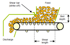
Identifying the hopper shear length is a key component for correctly sizing and selecting an apron feeder and drive system (motor). But, how can this be determined? The hopper shear length is the dimension from the back plate of the hopper at the skirt line to the shear bar located at the exit end of the hopper. It sounds very simple, but it is key to note that this should not be confused with the dimension at the top of the hopper where material is loaded.
The goal of finding this measurement of the hopper shear length is to establish the actual shear plane line of material and where material inside the skirts is separated (sheared) from the material inside the hopper (L2). The resistance to shear the material is typically estimated to be between 50-70% of the total force/power. This calculation of the shear length will result in either insufficient power (lost production) or excessive power (rising operating expenses (opex)).
How do I find the optimal length of my apron feeder?
Spacing of equipment is essential to any plant. As mentioned before, apron feeders can be installed on an incline to save space. Selecting the correct length of an apron feeder will not only reduce capital expenditure (capex), it will also reduce power consumption and opex.
But how is the optimal length determined? The optimum length of an apron feeder is one that can fulfil the required duty in the shortest length possible. However, in some cases for an operation, the choice of feeder might want to be a little longer to “convey” materials to reach downstream equipment and eliminate a transfer point (and unnecessary costs).
To determine the shortest and optimal feeder possible requires flexibility in the layout of positioning the apron feeder under the hopper (L2). After determining the shear length and bed depth, the overall length can then be minimised just enough to prevent what is referred to as “self-flushing” over the discharge end when the feeder is idle.
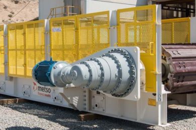
I properly selected my apron feeder, but what about my drive system?
Selecting the proper drive system for your apron feeder will depend on the operation and goals of the feeder. Apron feeders are designed to be ran at variable speeds to extract from storage and feed downstream at a controlled rate of speed for maximum efficiency. The material could vary depending on factors such as the season of the year, orebody, or blasting and blending patterns.
The two types of drives suited for variable speeds are a mechanical drive using a gear reducer, inverter duty motor and variable frequency drive (VFD), or hydraulic motor and power unit with a variable pump. Today, variable speed mechanical drives have been proven as the preferred drive system due to the advancements in technology and capex benefits.
Hydraulic drive systems do have their place but are not seen as the ideal option between the two variable drives.
This Q&A was taken from a series of Metso blogs on apron feeders. For more information, please follow these links:
https://www.metso.com/blog-hub/mining-minds/feeding-the-facts-part-1-apron-feeder-basics/